Computer Graphics I
Rendering Competition 2003/04
Participant: Dominik Schultes
<mail@dominik-schultes.de>
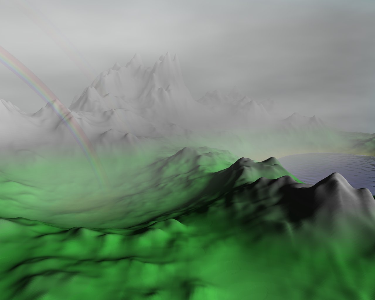
Title of the image: Wetterumschwung (change in the
weather)
download the source code
(click on the image to view it in full resolution)
Introduction
The program "LandscapeCreator" creates the model (a NFF file), which is stored in
the Data directory. Due to its size (about 250 MB) the NFF file is
not included, but has to be generated. After the model has been
created, the program "MicroTrace" can be used to render the
image. No command line arguments are required. The NFF file in the
Data directory is used as default input. The output is written to the
Data directory as well. Thus, the following steps have to be performed in order to
create the image:
cd LandscapeCreator
make
./createLandscape
cd ../MicroTrace
make
./MicroTrace
The script "run" contains these commands
so that you can just call it and everything is done automatically.
System Requirements
- Linux kernel 2.4.19
- g++ compiler 3.2
- 300 MB hard disk capacity
- 400 MB main memory
- a fast processor or some patience
Topics
1) Modeling - Fractal Geometry
Effect
The whole landscape (the mountains, the hills, the lake) has been
modeled with the help of fractals. Furthermore, the fog and the waves
on the lake base on fractals, too (see "3) Volume Rendering - Integrated
Intensity Volume Rendering" resp. "2) Texturing - Bump Mapping").
Realization
A height field is created with the help of a multifractal function
adopted from [5]. Everything below a given sea
level is interpreted as water, everything above is assigned a color
according to a color map (depending on the height). In order to speed
up the rendering process (without losing quality), more triangles are
produced in the foreground than in the background.
Source Code
All files in the directory "LandscapeCreator" are relevant. The most
important ones are:
The used fractal function can be found in Shared/Fractals/fractal.h.
2) Texturing - Bump Mapping
Effect
The waves on the lake.
Realization
The waves on the lake have been created using Bump Mapping as
described in the lecture and in [1]. Again, the
idea is taken from [5]. A bump map is computed
with the help of a simple fractal function. The points on the water
surface are displaced temporarily according to the bump map, and the so
perturbed surface normals are computed and stored; then the modification of the
surface points is discarded. A subclass of "Triangle", named
"BumpedTriangle", represents a triangle of the water surface. It
stores additionally the perturbed surface normal and the method
"GetNormal" returns this normal.
Source Code
Again, the used fractal function can be found in Shared/Fractals/fractal.h.
3) Volume Rendering - Integrated Intensity Volume Rendering
Effect
The fog.
Realization
A model of an atmosphere has been added. The atmosphere consists of
particles which are arranged in a 3-dimensional regular grid. Each
particle has a transparency and a color. (In this image the fog is
situated behind a specific diagonal (which crosses the lake), each
particle has the same transparency (apart from a small area where the
fog starts) and the color (the grey tone, r=g=b) is assigned with the
help of a fractal function (adopted from [5]).) The ray tracing process is enhanced in
the following way. Firstly, the color of the hit point is computed as
usual. Secondly, the color and transparency of the atmosphere is
computed. Finally, the color of the hit surface is weighted by the
transparency of the atmosphere and added to the color of the
atmosphere.
The color and transparency of the atmosphere is computed with the help
of the volume visualization and volume rendering techniques as
described in [11]. ([15] was
helpful, too.) Principally, an integration of the scalar field
intensities along the ray should be performed. As an exact solution of
the integral is much too expensive, several sample points along the
ray (between the camera and the hit point) are chosen and a relatively
simple numerical integration is performed. (The sample points are
chosen regularly (the distance between two sample points is always the
same).) In order to determine the color and transparency of an
arbitrary point in space, the 8 neighbouring particles in the
3-dimensional regular grid are considered and a trilinear
interpolation is performed. Basically, the numerical integration is
done by the following front-to-back approach:
transparency := 1

intensity := 0

for u:=1 to n do

  intensity += transparency * intensity[u] * (1 - transparency[u])

  transparency *= transparency[u]

  if (transparency < EPSILON) then break
Source Code
The directory "MicroTrace/Atmosphere" contains most of the relevant
files. The most important one is MicroTrace/Atmosphere/AbstractAtmosphere.hxx,
which contains the volume rendering functionality.
The file MicroTrace/SceneSpecific/MyAtmosphere.hxx
contains the initialization routine for the atmosphere that is used in
this image.
Again, the used fractal function can be found in Shared/Fractals/fractal.h.
4) Surface Shading - Refractive Transparency (with Dispersion)
Effect
The primary rainbow and the very faint secondary rainbow.
Realization
The idea is taken from [15]. As there are very many
raindrops and the consideration of multiple refraction and
reflection processes is quite difficult, a rainbow-specific approach
is chosen. The angle between the direction of the sun light and the
viewing direction is computed. If this angle is between a given
minimum and a given maximum angle (around 42 degrees for the primary
bow and around 51 degrees for the secondary bow), the wavelength of
the light is computed - 380 nm (violet) for the minimum angle, 780 nm
(red) for the maximum angle, and values in between according to the
angle; for the secondary bow the order of the colors is inverted.
Finally, the wavelength is transformed into a color (rgb-values),
which is weighted by a given transparency. The conversion from
wavelength to rgb-values is adopted from [16].
Source Code
The functionality is encapsulated in
MicroTrace/Atmosphere/Rainbow.hxx. Both rainbows that are used in
this image are instantiated in
MicroTrace/SceneSpecific/MyAtmosphere.hxx [line 25].
References
[1] J. F. Blinn. Simulation of Wrinkled
Surfaces. Computer Graphics (Proceedings of SIGGRAPH 78),
12(3):286-292, 1978.
[5] D. Ebert, F. K. Musgrave, D. Peachey, K. Perlin,
and S. Worley. Texturing and Modeling: A Procedural Approach.
Morgan Kaufmann, third edition, 2002.
[11] M. Meißner, C.M. Wittenbrink, R. Westermann,
and H. Pfister. Volume Visualization and Volume Rendering
Techniques. Eurographics tutorial, 2000.
[15] M. Inakage. Volume tracing of atmospheric
environments. The Visual Computer, 7:104-113, 1991.
[16] C. Zimmermann.
http://www.massimo18.ch/download/MyColor.java, 19. 12. 2003.